
United Kingdom
181 Posts
Posted - 02/12/2011 : 22:04:44
Right...a bit more progress!
A few voids and hollows were filled in the "bog" fillets and sanded smooth...
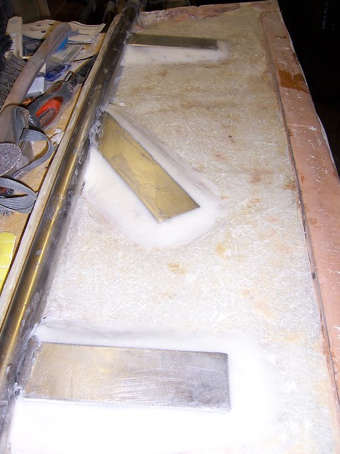
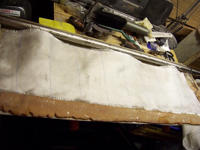
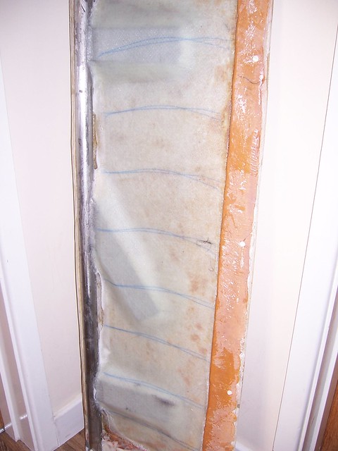
The following shots show the layup of the glass. In these pictures, all the layup is dry, however each layer was wet out on a smooth plastic surface with squeegee, both sides, and applied in turn. The first 3 layers is fairly heavy biaxial 150mm tape, trimmed to size. Smallest first...
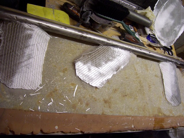
Then bigger...
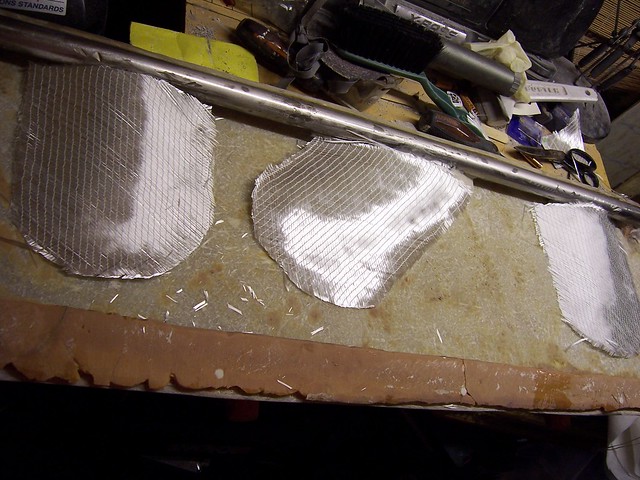
Then a layer of tape running the full length of the rudder...
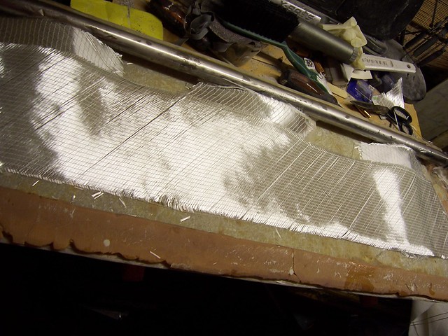
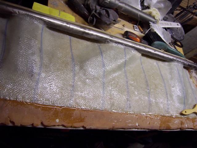
Followed by 2 layers of glass weave...
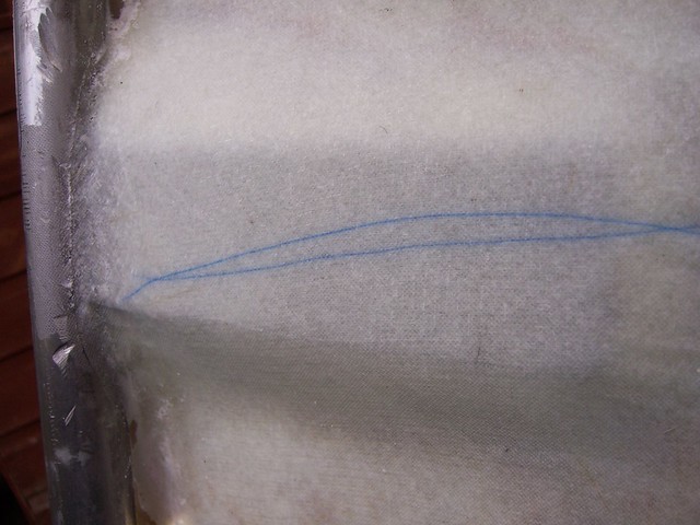
Each layer of laminate was wet-out off the rudder, and the final layup looks like this...
Next on was a layer of peel ply...
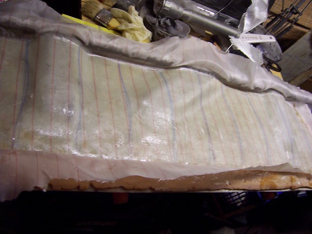
...and then it's a layer of breadwrap, bleed cloth and into the vacuum bag, made from polythene and gaffer tape. This shot was taken a few minutes after switching the pump on...the vacuum did get tighter, however the resin is already starting to bleed through so it's nicely wet-out!
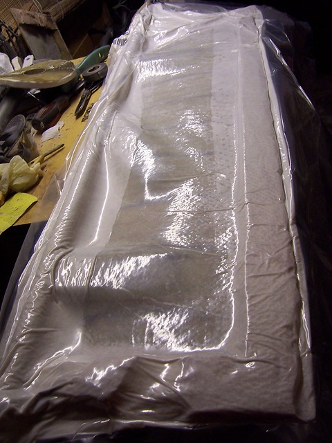
And here is the vacuum pump doing it's thing. I will leave it overnight and it should all be perfectly consolidated in the morning.

Next job to stick the two halves back together!
Iain C
United Kingdom
181 Posts
Posted - 03/12/2011 : 09:42:13
Vacuum pump off this morning, peel ply off and out of the vac bag, and into a nice warm house for the final cure. Very pleased with the result!
Close up of the finish...no voids or excess resin.
Iain C
United Kingdom
181 Posts
Posted - 18/12/2011 : 21:02:21
Progress has been slow. OK, confession time, I've had to take the angle grinder to all of the above work!
Yep, you guessed it, the tiller was out of line. Not much, but enough that I knew it was out, and I dare say Raymondo the Raymarine might have got a bit confused too. If the existing tangs get removed to be re-welded, and the angles of the tangs change a teeny bit, it's easy to drop a clanger. The orignal tangs were welded on at various angles, the new ones were much straighter, and that's where I probably went wrong.
So, as a word of warning I'll explain how I've got it right the second time. I used a bicycle workstand to keep the shaft totally upright, and I pinned a plumb line to the exact centre point of the tiller.
With the centre of the shaft marked up with permament marker, I aligned it over a join in the kitchen floor tiles (checked with a known straight edge first!), and ensured that the plumb line from the end of the tiller was over the same join. Make sure the tiller is clamped on, and there's no slop. The port rudder side was bogged up and put in place. Clamps were applied to keep it in place and everything re-checked. Leading edge and trailing edge splits, centre of shaft, and plumbline all over the same line. Then carefully sighting from the front, and the plumbline nicely cutting the shaft and the tiller "in half" and matching the leading edge split exactly...not forgetting to check the the shaft was vertical in all planes with a spirit level. Finally, when semi-cured, I removed the clamps and clamped the other half of the rudder on, and everything looks good.
It was annoying, however it's nearly sorted and it was far better to realise at this stage it was out, and fix it, than to have completely relaminated the thing and put it back in place! I hope I can save someone else the same error, and if anyone can think of a better way to align it (lasers perhaps?) please post it here!
Peter OD
United Kingdom
50 Posts
Posted - 19/12/2011 : 08:12:30
Iain
It's a horrible thing to happen, and I feel for your anger/anguish at the problem. However, for me, and I suspect others, you have almost certainly prevented the same mistake being made elsewhere; thanks for your honesty, and the fascinating and detailed description of the job. I wish you well. Peter (Sanda Isle)
davea
United Kingdom
18 Posts
Posted - 19/12/2011 : 20:05:30
I have been following this thread with some interest as a lot of the materials are used where I work in the marine industry.
Just going off the subject a little, do any owners suffer with tiller vibration when under power?
another question, why tangs and not a couple of plates instead? surely plates would be stronger, more surface area.
Edited by - davea on 19/12/2011 20:30:29
Iain C
United Kingdom
181 Posts
Posted - 20/12/2011 : 09:49:38
Well we are now back to where we were in the last picture, and I actually changed the layup this time, putting in a bit of 0/90 in the middle between some of the 45/45. It now finishes with two layers of 45/45 with an overlap running over the ends of the tangs, and not bothering with the layers of 0/90 which went on last. So I'm actually happier with it now so it's not a big deal, and it was certainly an easier thing to sort out than repair job I could have had if the steering had failed!
With regards to a big plate v a tang, I'm not an engineer but if you had something on your dinner plate you wanted to split open, you'd use your knife, not the points of your fork. So I guess the same principle applies with the rudder...with tangs the turning force of the shaft is absorbed into the structure of the rudder much better and the "splitting" force is reduced. Plus the weight of a big s/s plate would be huge. I guess it could work if you had a plate with very big holes drilled in it...but correctly welded tangs out of 316 stainless will be more than up to it.
Rudder vibration is almost certainly a worn tube or bottom bearing.
Next job, put the two halves back together!